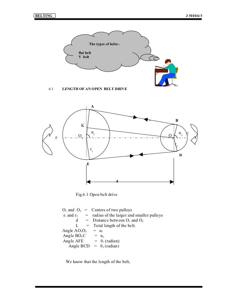
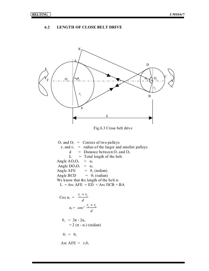
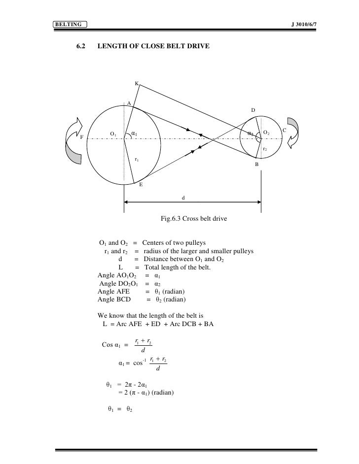
It is always greater than 180 for a cross belt. 91 7900123134 Email id.
I have some pics but i wont post themBob.

Minimum contact angle pulley for v belt. 12112011 30-42 degrees depending on the size of belt and the pulley dia. The distance between the centre of the pulleys is 600 mm the included angle of the pulley groove 40 the coefficient of friction between the belt and pulley is 04 and the ultimate strength of the belt is 8 kN. Pretension belts with the proper recommended tension.
Idler location is on the slack side span of the belt drive Diameter for inside toothed idler must be of the diameter ofthe small pulley in the drive Idler must be mounted on a rigid supportIdlers both flat and toothed should be uncrowned with a minimum arc of contact. Compute the contact angle beta between the belt and pulley or cylinder. 41 MAXIMUM POWER WITH NO BELT SLIP.
Compute the maximum torque transfer available from a pulley system. Classical V-Belts 03 Minimum Pulley Diameter Table 3. Compute the tension differential on either side of the belt or cylinder for both flat and v-belts.
If we require a power of 100 Watts Nms while the input is rotating at a rate of 1000 rpm and the output is rotating at a rate of 14286 rpm what is the required resting tension in the beltAssume contact angles of approximately 180 degrees. For the same pulley diameter and same centre distance. 09092015 Belt manufacturers recommend that the tension ratio for a system with 180.
Power transmission is higher in case of cross belt drive because of higher angle of contact or angle of rape whatever you want to say. The coefficient of friction between the belt material and the pulley is 5. For a flat belt drive the friction between the belt and pulley for a small segment of belt is while for a V-beltsheave with a 38.
13012017 A V-belt is used to transmit power from this pulley to a second pulley 400 mm diameter against a load of 200 Nm. This ratio changes with the angle of contact on the small sheave. Of contact on each sheave should be no tighter than 51 when a new belt has been installed and no looser than 81 after the belt has run-in.
We also have Pulley 2 and we know the diameter of this pulley as well. The arc of contact correction factor corrects the power rating of the V-belt for pulleys where the arc of the contact differs from 180 degrees. Minimum Pulley Diameter in mm Figure 3.
Multi vs Single Stage The total contact angle in a belt system always adds up to 360. Remember Pulley 1 is always going to be the largest pulley you have and youll see this as we go through the calculations shortly. 24082012 At least one pulley should be adjustable to allow for belt installation and tensioning.
Service factor c 2. Angle of contact in case of a cross belt drive refers to the angle made by the portion of the belt in contact with the pulley. In case of open belts it is less than 180.
The size of the correction factor is determined from the following equation. Torque and rotational speed will vary according to pulley diameters. Chain Drives Kinematics.
As a result of the relative motion between belt and pulley the belt. Angle 38 degrees it can be shown that at 180 degrees of wrap a practical level of V-Belt operating tension can be achieved with a 51 ratio between the tight side tension and the slack side tension. Make at least one pulley in the belt drive adjustable to allow for belt installation and tensioning.
V πND P v F11 -e-θ. 28112017 The proper tension for the belt is the minimum tension required to prevent the belt from slipping at maximum load. Formula 2 below establishes the static tension required to.
26052019 Now we already know the size of the pulley either from the manufacturers data or we can go out into the building and actually measure this. The larger dia the pulley the more degree on the angle. Center Distance and Belt Length The relation between center distance and length is given by the following formula.
Also note that in a properly designed belt drive there should be a minimum of six teeth in mesh and at least 60. 02092018 Ideally the maximum force to be transmitted corresponds to the maximum static friction force acting between the belt and pulley. Therefore the contact angle per pulley in a properly designed 2-pulley system will always provide greater contact length than an equivalent 3-pulley system.
Angle the friction would be 292. This is important to maximize belt life and prevent ratcheting of the belt or tooth jumping. A good guideline in the absence of any other information is to use a spring scale and press down on the belt in the approximate center of its span on the tight side to deflect the belt 164 per inch of span length and.
The same hub load and stress in the tensile members gives V-belts nearly 3x the friction of flat belts. 08062019 Contact angle or wrap angle between the belt and pulley is comparatively small always below 180. When a belt rope or cable is wrapped around an object there is potential for flexible belt friction.
Length of the open belt is smaller as compared to cross belt. Velocity Ratio Of Belt Drive Belts Ropes. If the force to be transmitted is greater than the static friction force the belt slips over the pulley and only the lower sliding friction force is effective called sliding slip.
The service factor takes into account the daily service period and the type of drive units and driven machine. Of belt wrap around the drive pulley. A minimum of six teeth in mesh and at least 60 degrees of belt wrap are recommended.
Make sure shafts and pulleys are aligned to prevent belt. Contact angle between the belt and pulley is comparatively large always above 180. Center Distance and Belt Length The minimum pulley diameters recommended for standard V-belts are shown in Table 3.
The power transmitted by a pulley was shown to be P πND F1 - F2 vF1 - F2 When the belt starts to slip the force ratio is F1 F2 eθ Substituting for F2 we have P πNDF11 -e-θ It may be easier to use belt velocity instead of wheel speed.
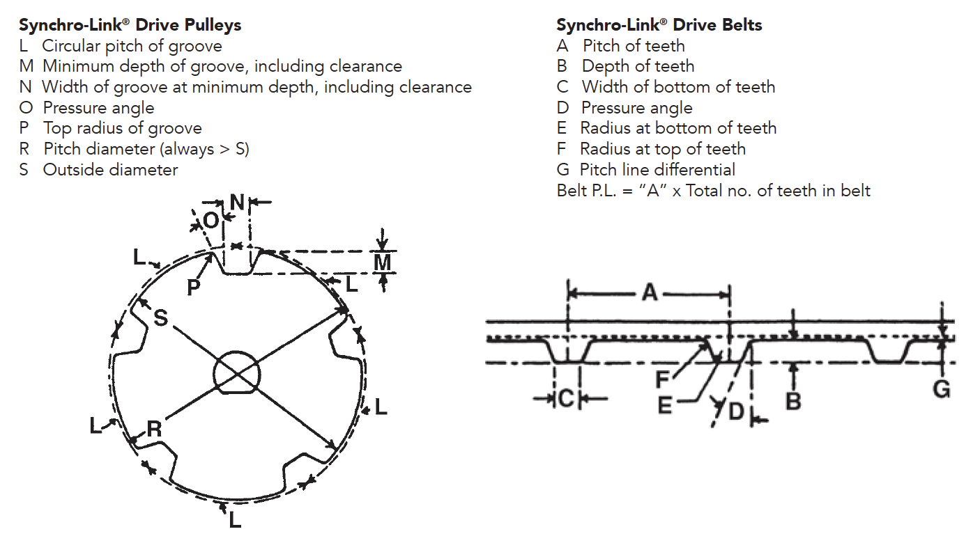 Synchro Link Trapezoidal Mpb Timing Belt Pulleys
Danotes V Belt Drives Kinetics And Fatigue
 Belt Drives An Overview Sciencedirect Topics
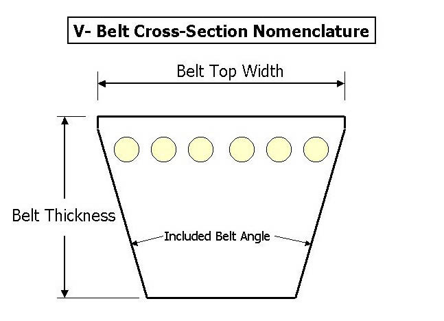 V Belt Pulleys Selection Guide Types Features Applications Engineering360
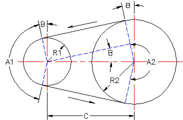 V Belts Design Requirements For Power Requirements Angle Between Sheave Engineers Edge Www Engineersedge Com
 A Shows Cross Sections Of The Belt And The Pulley Groove The Download Scientific Diagram
 Belt Sliding In Pulley Grooves A Cross Section And Acting Forces Download Scientific Diagram
Https Www Bestorq Com Library Techinfo Techinfo Theory Pdf
